Icom IC-7851
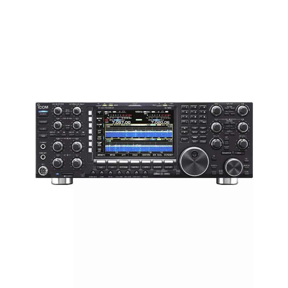
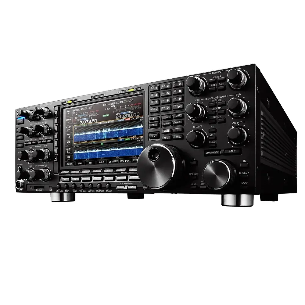
Icom IC-7851 adalah radio HF (High Frequency) atau radio SSB (Single Side Band) dengan kualitas terbaik dan menetapkan standar baru di dunia komunikasi amatir. Baik untuk kontes, DX-ing atau komunikasi harian, IC-7851 menghadirkan kejernihan dan kekuatan yang luar biasa.
Fitur-Fitur Icom IC-7851
RMDR: 110dB Menetapkan Standar Baru
RMDR (Reciprocal Mixing Dynamic Range) menunjukkan seberapa besar sinyal yang tidak diinginkan, yang terletak pada frekuensi tertentu dari jalur penerimaan, dapat menaikkan tingkat kebisingan sebesar 3 dB.
Icom IC-7851 menetapkan tolok ukur baru dengan nilai RMDR sebesar 110dB pada offset 1 kHz. Keunggulan ini dicapai melalui perbaikan desain Local Oscillator yang secara signifikan mengurangi phase noise.
Filter Roofing 1,2kHz Optimal
Radio SSB ini menggunakan desain up-conversion yang sudah terbukti andal dalam menekan gangguan bayangan dan distorsi. Dengan penambahan filter roofing 1,2kHz yang baru, kinerja selektivitas sinyal meningkat drastis terutama saat menghadapi sinyal-sinyal yang berdekatan secara frekuensi.
Desain Local Oscillator Jernih
Dengan menggabungkan teknologi Direct Digital Synthesizer (DDS) dan Phase Locked Oscillator, IC-7851 menghasilkan rasio C/N (Carrier to Noise) yang jauh lebih unggul dibandingkan IC-7800.
Karakteristik Phase Noise
Desain Local Oscillator baru dalam IC-7851 mencatat peningkatan signifikan dalam pengurangan phase noise. Dibandingkan IC-7800, IC-7851 menunjukkan peningkatan hingga 20dB pada offset 10 kHz dan lebih dari 30dB pada 1 kHz.
Spektrum Scope yang Lebih Baik
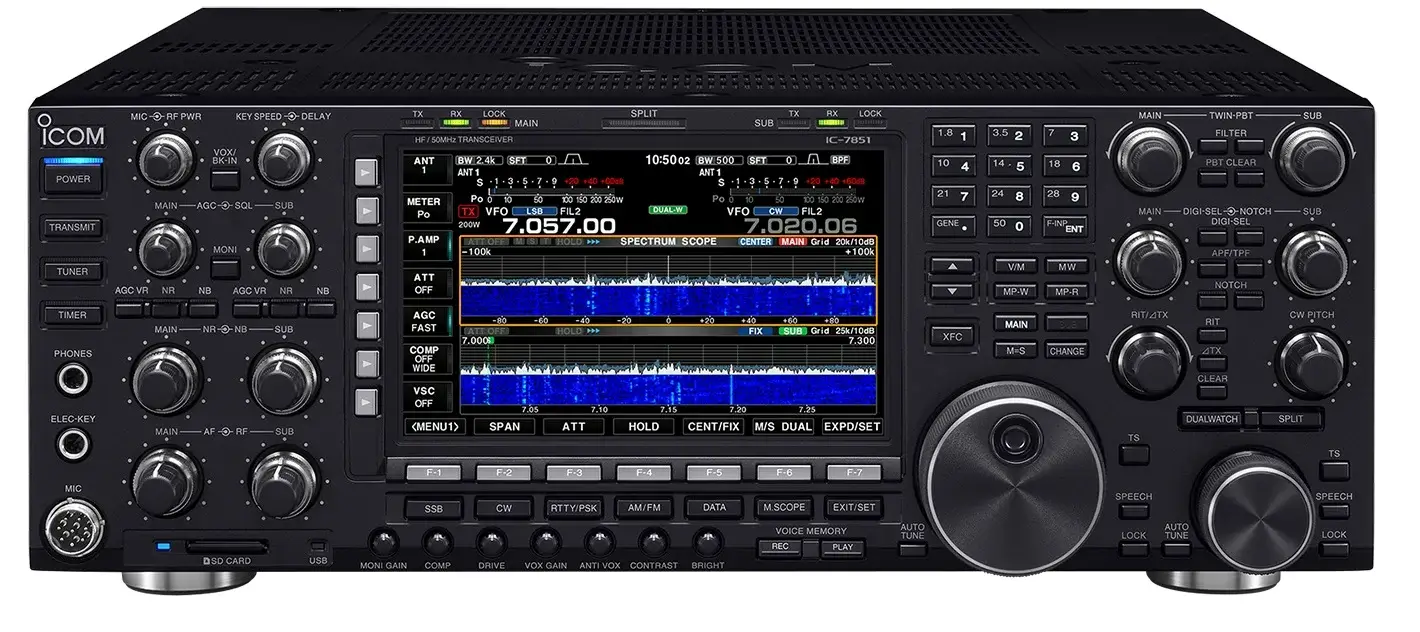
Menggunakan teknologi dari IC-7800, radio SSB Icom ini menggunakan DSP terdedikasi untuk FFT spectrum. Dengan prosesor 2250 MFLOPS, spektrum scope kini lebih cepat, lebih akurat, dan mendukung fungsi dual scope.
Fungsi Audio Scope
Fitur audio scope menampilkan bentuk gelombang (oscilloscope) dan FFT untuk audio penerimaan dan transmisi sekaligus. Anda dapat menyesuaikan kompresi, EQ, dan gain microphone secara langsung. Saat menerima, filter width dan penempatan notch dapat divisualisasikan untuk menghapus sinyal gangguan dengan akurat.
Fungsi Dual Scope Icom IC-7851
IC-7851 memperkenalkan dual scope untuk memantau dua receiver dalam tampilan spektrum yang terpisah.
Tampilan Waterfall Spektrum Resolusi Tinggi
Tampilan waterfall merekam kekuatan sinyal dari waktu ke waktu, menampilkan sinyal lemah yang sulit terlihat pada tampilan spektrum biasa. Dipadukan dengan mode layar lebar dan attenuator, fitur ini membuat pelacakan sinyal lemah menjadi lebih mudah. IC-7851 juga mendukung output DVI-I untuk tampilan layar eksternal yang lebih besar.
Kontrol Klik
IC-7851 mendukung pengendalian spektrum secara langsung melalui perangkat, seperti: mouse USB, trackball atau touchpad. Anda dapat mengklik sinyal pada tampilan spektrum untuk langsung mendengarkannya. Mode fix/center dan kecepatan sweep dapat dikontrol secara intuitif.
Titik Intersep Orde Ketiga +40dBm
Untuk performa penerimaan terbaik, IC-7851 mempertahankan +40dBm IP3 dengan rentang dinamis 110dB. Seluruh sirkuit analog dirancang ulang untuk menyatu sempurna dengan sistem DSP.
Pergantian BPF Menggunakan Relay Mekanis
Alih-alih menggunakan dioda PIN, IC-7851 menggunakan relay mekanis berkualitas tinggi untuk beralih antara band pass filter. Pendekatan ini menghilangkan distorsi sekunder dan meningkatkan kejernihan sinyal sejak tahap awal pemrosesan RF.
Empat Filter Roofing IF Pertama
Radio berfrekuensi tinggi ini menyediakan empat filter roofing IF pertama dengan lebar 15kHz, 6kHz, 3kHz, dan 1.2kHz. Filter ini bekerja menyesuaikan mode operasional.
Digi-Sel Preselector
Digi-Sel Preselector bekerja pada frekuensi 1,5–30 MHz dan secara otomatis menyaring sinyal gangguan dari luar pita, seperti stasiun radio siaran kuat atau sistem multi-multi. Bandwidth preselector akan tetap terpusat pada frekuensi kerja yang diinginkan. Frekuensi tengah preselector ini juga dapat diatur secara manual melalui tombol tuning di panel depan.
Tenaga DSP Ganda Tiga Unit (Triple DSP Power)
IC-7851 dilengkapi tiga prosesor DSP terpisah dengan konversi AD/DA 24-bit. Satu unit DSP digunakan untuk tampilan spektrum, sementara dua lainnya menangani sirkuit penerima dan pemancar.
Sistem AGC Ganda (Dual AGC Loops)
IC-7851 menggunakan dua loop AGC (Automatic Gain Control) yang bekerjauntuk menjaga kestabilan penerimaan. Loop pertama mencegah kejenuhan pada penguat IF pertama. Sedangkan loop kedua bekerja setelah filter digital.
Image Rejection Mixer
Dengan sistem konversi ganda dan penggunaan mixer D-MOS FET serta image rejection mixer tahap kedua, IC-7851 berhasil menekan distorsi dan sinyal palsu.
Unit OCXO dengan Performa Tinggi
IC-7851 menggunakan Oven Controlled Crystal Oscillator (OCXO) dengan deviasi hanya ±0,05 ppm pada suhu 0–50°C. Bahkan pada frekuensi 50 MHz, deviasi frekuensi hanya sekitar 2,5 Hz. Radio ini juga mendukung input/output referensi frekuensi 10 MHz untuk penyelarasan yang lebih akurat.
Power Output Icom IC-7851 Besar
Dengan rangkaian penguat daya push-pull MOS-FET pada tegangan 48V DC, IC-7851 menghasilkan daya keluaran 200 watt penuh dan stabil bahkan untuk penggunaan terus-menerus. Sistem pendinginan internal yang efisien mencegah kelebihan panas.
Knob Dial Utama dari Aluminium Solid
Knob utama radio SSB ini dibuat dari balok aluminium padat.
Penerima Ganda (Dual Receivers)
IC-7851 memiliki dua sistem penerima dari input antena hingga keluaran audio. Masing-masing penerima memiliki performa setara dan dapat disalurkan ke headphone stereo atau speaker eksternal secara terpisah maupun gabungan.
Mode Digital Icom IC-7851
Berikutnya, radio frekuensi tinggi ini dapat menggunakan mode operasional RTTY, PSK31, dan PSK63 secara langsung tanpa memerlukan komputer tambahan. Modulator dan demodulator bawaan dapat diakses melalui tombol fungsi atau dengan keyboard USB opsional. Semua log komunikasi dapat disimpan dalam kartu memori SD.
Filter IF Digital
Fitur filter IF digital untuk menyesuaikan lebar filter dari 50 hingga 3600 Hz dengan karakteristik tepi tajam atau lembut. Pengaturan ini bisa disimpan dalam tiga preset (Wide/Mid/Narrow) yang dapat dipanggil berdasarkan mode pemakaian.
Manual Notch Digital
Filter notch digital manual membantu menghilangkan gangguan, seperti: sinyal carrier AM dan heterodyne. Filter ini memiliki tiga bentuk penyesuaian dan dapat memberikan peredaman lebih dari 70dB.
Digital Twin PBT (Passband Tuning)
Fitur Digital Twin PBT memberi keleluasaan untuk mengatur lebar dan posisi jalur passband pada IF digital. Anda dapat secara halus memotong gangguan di luar sinyal utama.
Pengurangan Kebisingan Icom IC-7851
IC-7851 memiliki noise reduction digital adaptif dengan 16 tingkat pengaturan. Berbasis DSP berkecepatan tinggi, sistem ini mampu secara efektif memisahkan sinyal dari derau (noise).
Digital Noise Blanker Otomatis
Fitur Digital Noise Blanker otomatis pada radio ini memberikan peredaman gangguan tipe pulsa. Saat menggunakan filter roofing 1,2 kHz, sistem secara otomatis menyesuaikan tingkat blanking terbaik.
Transmit Bandwidth Digital dan Equalizer Audio
Anda dapat menyesuaikan kualitas suara TX dan RX dengan filter digital TBW dan equalizer bass/treble. Filter pemancar memiliki tiga preset (Wide/Mid/Narrow) dengan cut-off yang dapat disesuaikan.
Kompresor Ucapan RF Digital
Kompresor suara RF berbasis DSP 32-bit memberikan kekuatan transmisi tambahan tanpa mengorbankan kejernihan suara. Fitur ini sangat membantu untuk menembus kondisi noise tinggi saat kontes atau DX.
Slot Kartu Memori SD
Kartu SD digunakan untuk menyimpan profil operator, keyer suara digital, log komunikasi digital (RTTY/PSK), tangkapan layar, dan pengaturan lain.
Perekam Suara Digital
Fitur ini melakukan perekaman audio RX dan TX ke dalam SD atau USB hingga 9 jam dengan kapasitas 2GB. Cocok untuk dokumentasi QSO penting atau pelacakan sesi operasi dalam kontes.
Keyer Memori Icom IC-7851
IC-7851 menyediakan 8 memori keyer untuk mode CW dan digital serta 4 untuk fonetik dengan fitur, seperti: auto repeat, penghitungan serial kontes, dan fungsi singkat Morse. Ini sangat membantu untuk operasi cepat saat kompetisi.
Tuner Antena Otomatis Disempurnakan
Tuner internal memiliki memori pengaturan tuning untuk respon cepat saat berpindah frekuensi. Tuner otomatis ini mengoptimalkan pengaturan SWR untuk setiap kondisi.
Saklar Antena Internal Icom IC-7851
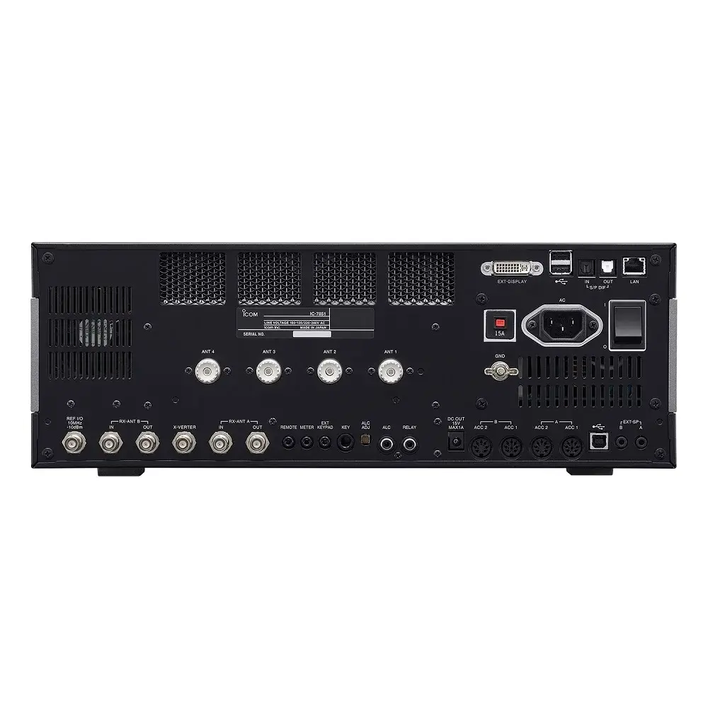
Berikutnya, radio SSB Icom ini menyediakan 6 port antena termasuk 2 untuk penerima saja. Fitur memori saklar antena otomatis untuk perubahan pengaturan TX/RX berdasarkan band yang dipilih.
Konektivitas Lebih Lengkap
Radio ini mendukung berbagai koneksi ke komputer melalui USB, S/P DIF, dan Ethernet. Tersedia USB audio, keying digital (CW, RTTY), dan CI-V. Anda juga dapat mengontrol IC-7851 secara jarak jauh melalui Internet menggunakan fitur LAN internal.
Update Firmware
IC-7851 mendukung update firmware melalui USB atau kartu SD agar perangkat tetap relevan dengan fitur dan peningkatan terbaru dari Icom.
Kontrol Jarak Jauh Sederhana (RS-BA1 Opsional)
IC-7851 mendukung remote base operation melalui software RS-BA1, tanpa komputer tambahan di lokasi rig. Tiga akun pengguna bisa disetel dengan kontrol penuh atas fungsi radio, spektrum, dan perekaman suara secara jarak jauh.
Fitur Lain Icom IC-7851
IC-7851 dilengkapi berbagai fitur tambahan yang mendukung kinerja keseluruhan, baik dari sisi penerimaan, transmisi, hingga kemudahan pengoperasian:
Antena
- Tersedia konektor BNC khusus untuk antena penerima atau attenuator eksternal.
- Mendukung pengaturan antena dengan kontrol saklar antena otomatis.
Penerima
- Penerima cakupan umum dari 30 Hz hingga 60 MHz (beberapa rentang frekuensi tidak dijamin).
- Dua jenis preamp:
- Preamp 1 untuk peningkatan karakteristik intermodulasi.
- Preamp 2 sebagai penguat gain tinggi untuk band atas.
- Attenuator 7 tingkat: 3, 6, 9, 12, 18, 21 dB dan OFF.
- Mixer khusus 50 MHz menggunakan Quad FET.
- Filter puncak ganda (Twin Peak Filter) untuk penerimaan sinyal RTTY yang lebih baik.
Pemancar
- Kompresor suara meningkatkan daya bicara rata-rata (mode SSB).
- Fungsi monitor transmisi mempermudah pemantauan suara anda sendiri.
- Mendukung 50 sub tone (CTCSS) untuk akses repeater.
- Fitur VOX (voice operated transmission).
- Pengaturan daya pemancar semua mode tersedia.
CW (Morse)
- Bentuk gelombang CW dikontrol oleh DSP yang memberikan nada halus dan tajam.
- Keyer elektronik multifungsi: kecepatan, rasio dot/dash, tipe keyer, waktu naik, polaritas paddle dapat disesuaikan.
- Tersedia CW pitch control dari 300–900 Hz (dengan kenaikan 5 Hz).
- Mode CW reverse untuk penerimaan sisi USB.
- Jack keyer ganda di panel depan dan belakang.
- Mendukung full break-in dan semi break-in.
- Fungsi CW/AM auto tuning membantu menyelaraskan sinyal dalam rentang ±500 Hz.
- Filter audio puncak (APF) dengan bentuk suara lembut dan tajam.
Pengoperasian Icom IC-7851
- Mode pengaturan (Set Mode) untuk pengaturan cepat dan fleksibel.
- Memo Pad menyimpan hingga 10 frekuensi dan mode operasi.
- Fungsi Quick Split dan Split Lock untuk pemisahan TX/RX instan.
- Quick Dualwatch untuk memantau dua frekuensi sekaligus.
- Tuning sinkron SSB/CW.
- RIT dan ΔTX dapat disesuaikan hingga 9.999 kHz.
- Jam UTC/Lokal dan fungsi pengatur waktu (timer).
- Tuning pitch 1 Hz dan tampilan presisi tinggi.
- 101 channel memori dengan nama hingga 10 karakter.
- Voice synthesizer internal mengumumkan frekuensi, mode, dan level S-meter.
- Scan: scan program, scan memori, scan memori pilihan, VSC scan, dan Δf scan.
- Fungsi auto tuning step, penguncian dial (dial lock), dan kontrol ketegangan dial utama.
- Beep pinggir band yang dapat diprogram.
- Konektor S/P DIF untuk input/output digital.
- Konektor transverter BNC untuk ekspansi frekuensi.
- Konektor speaker eksternal untuk penerima utama dan sekunder.
- Fungsi rata-rata gelombang FFT untuk decoder PSK dan RTTY.
- Fitur screen saver untuk melindungi tampilan.
Spesifikasi Icom IC-7851
| General | ||
| Frequency coverage*1 | ||
| U.S.A. Version | Europe Version | |
| Receiver | 0.030–60.000MHz*² | 0.030–60.000MHz*² |
| Transmit | 1.800–1.999MHz | 0.1357–0.1378MHz |
| 3.500–3.999MHz | 1.810–1.999MHz | |
| 5.255–5.405MHz*² | 3.500–3.800MHz | |
| 7.000–7.300MHz | 7.000–7.200MHz | |
| 10.100–10.150MHz | 10.100–10.150MHz | |
| 14.000–14.350MHz | 14.000–14.350MHz | |
| 18.068–18.168MHz | 18.068–18.168MHz | |
| 21.000–21.450MHz | 21.000–21.450MHz | |
| 24.890–24.990MHz | 24.890–24.990MHz | |
| 28.000–29.700MHz | 28.000–29.700MHz | |
| 50.000–54.000MHz | 50.000–52.000MHz | |
| Mode | USB, LSB, CW, RTTY, PSK31/63, AM, FM | |
| No. of memory channels | 101 (99 regular, 2 scan edges) | |
| Antenna connector | SO-239×4 and BNC×2 (50Ω unbalanced (Tuner off)) | |
| Operating temp. range | 0°C to +50°C; +32°F to +122°F | |
| Frequency stability | Less than ±0.05ppm (0°C to +50°C @ 54MHz, after warm up) | |
| Frequency resolution | 1Hz (minimum) | |
| Power supply requirement | 85–265V AC | |
| Current drain | TX: 800VA (Max. power) | |
| RX: 130VA/120VA typ. (Max. audio/standby) | ||
| Dimensions (W×H×D, projections not included) | 425×149×435 mm; 16.73×5.87×17.13 in | |
| Weight (approximate) | 23.5 kg; 51.8 lb | |
| *1 Varies according to version. | ||
| *2 Some frequency bands are not guaranteed. | ||
| Transmitter | ||
| Output power | SSB/CW/FM/RTTY/PSK: 5–200W | |
| AM: 5–50W | ||
| Transverter connector (CW): More than –20dBm | ||
| Modulation system | SSB : Digital P.S.N. modulation | |
| AM : Digital low power modulation | ||
| FM : Digital phase modulation | ||
| Spurious emissions | HF bands: More than 60dB, | |
| 50MHz band: More than 70dB | ||
| Carrier suppression | More than 63dB | |
| Unwanted sideband suppression | More than 70dB | |
| ⊿TX variable range Microphone impedance | ±9.999kHz | |
| Microphone impedance | 600Ω (8-pin connector) | |
| Receiver | ||
| Receive system | Double conversion super-heterodyne system | |
| Intermediate frequencies | Main receiver: 64.455MHz/36kHz (1st/2nd) | |
| Sub receiver: 64.555MHz/36kHz (1st/2nd) | ||
| Sensitivity (typical) | SSB, CW, RTTY, PSK (BW=2.4kHz, at 10dB S/N) | |
| (HF: Pre-amp 1 ON, 50MHz: Pre-amp 2 ON) | 0.1MHz~1.7999MHz:0.5μV | |
| 1.8MHz~29.990MHz:0.16μV | ||
| 50MHz~54MHz :0.13μV | ||
| AM (BW=6kHz, at 10dB S/N) | ||
| 0.1MHz~1.7999MHz:6.3μV | ||
| 1.8MHz~29.990MHz:2μV | ||
| 50MHz~54MHz :1μV | ||
| FM (BW=15kHz, at 12dB SINAD) | ||
| 1.8MHz~29.990MHz:0.5μV (28–29.9MHz) | ||
| 50MHz~54MHz:0.32μV | ||
| Sensitivity for RED (Less than) | SSB (2.4 kHz): | |
| Preamp ON | 1.8–2.999 MHz 10 dBμV emf | |
| SSB, AM, FM: at 12 dB SINAD | 3.0–29.999 MHz 0 dBμV emf | |
| (EURO Version) | 50 MHz band –6 dBμV emf | |
| AM (4 kHz, 60% modulation): | ||
| 1.8–2.999 MHz 16 dBμV emf | ||
| 3.0–29.999 MHz 6 dBμV emf | ||
| 50 MHz band 0 dBμV emf | ||
| FM (7 kHz, 60% modulation): | ||
| 28–29.700 MHz 0 dBμV emf | ||
| 50 MHz band –6 dBμV emf | ||
| Squelch sensitivity | SSB, CW, RTTY, PSK: Less than 5.6μV (Pre-amp: OFF) | |
| FM: Less than 1μV (Pre-amp: OFF) | ||
| Selectivity | SSB (BW=2.4kHz, sharp):2.4kHz/-3dB 3.6kHz/-60dB | |
| CW/RTTY/PSK (BW=500Hz, sharp):500Hz/-3dB 700Hz/-60dB | ||
| AM(BW=6kHz):6.0kHz/-3dB 15kHz/-60dB | ||
| FM(BW=15kHz):12kHz/-6dB 20kHz/-60dB | ||
| Spurious and image rejection ratio | More than 70dB | |
| Audio output power | More than 2.6W (10% distortion, 8Ω load) | |
| RIT variable range | ±9.999kHz | |
| Antenna Tuner | ||
| Matching impedance range | HF bands: 16.7Ω to 150Ω unbalanced (VSWR better than 3:1) | |
| 50MHz: 20Ω to 125Ω unbalanced (VSWR better than 2.5:1) | ||
| Minimum operating power | HF bands: 8W, 50MHz band: 15W | |
| Tuning accuracy | VSWR 1.5:1 or less | |
| Insertion loss | Less than 1.0 dB (after tuning) | |
Aksesoris Standar Icom IC-7851
- Rak
- Kabel power AC
- Spare fuses
- Plugs
Aksesoris Opsional Icom IC-7851
- Microphone – HM-36
- Microphone meja – SM-30, SM-50
- Speaker – SP33, SP-34
- Converter – CT-17
- Remote kontrol – RS-BA1
- USB Remote Encoder – RC-26
- Amplifier -IC-PW1/IC-PW1EURO
Yoga Setiawan (verified owner) –
Barang dikirim dengan bagus, banyak pertanyaan dilayanin terus sama kk Novi